Spool

On the Pipe Spools tab, the Spool group contains tools for managing the spools that you have selected from the Spool List dialog (see List).
Assign To Space

When a pipe spool is created, normally it gets assigned to the hierarchically lowest logistics 3D space that contains (the most part of) the pipe object. (Assigning a spool group to a particular 3D space requires that the target space has the containment property "Can host spool groups" selected—see Properties of logistics containment.)
The choice of 3D space gets more complicated if the pipe object is not completely inside a single logistics 3D space, or if 3D spaces overlap and pipe object is completely or partly inside multiple 3D spaces.
In the Spool group, use the commands in the Assign To Space menu to manually manage how pipe spools are assigned to 3D spaces.
-
Current space — Assigns the selected spool to the active 3D space.
-
Alternative space — Opens a dialog for selecting an alternative 3D space to which to assign the selected spool.
-
Remove assign — Restores the original state of a spool that has been manually assigned to a specific 3D space.
Define

When a pipe spool is created, the inclusion of pipe parts in that particular spool is controlled by the spool generation rule (see Spools), and the naming of the spools is controlled by the spool numbering settings (see Pipe Spool Drawing).
In the Spool group, use the commands in the Define menu to rename spools and to manually manage how pipe parts are assigned to pipe spools.
-
Rename spools of pipelines — Renames all spools in the active main document. You are prompted to enter the number from which to start the renaming. See Renaming the spools of the active main document.
-
Manually rename selected spool — Allows entering a new name for the selected spool. See Renaming a spool manually.
-
Redefine selected spools — Recreates the selected spools to match the model. Removes user modifications (field weld markings, extra length markings), attributes, and check results.
-
Move parts to selected spool — Moves a user-defined set of parts to the selected spool. All parts to move must be in the same pipeline and 3D space as the target spool.
-
Create new spool — Allows the user to manually select the pipe parts from which to create a spool.
-
Reset weld IDs of active main document — This command resets weld IDs in the active main document, and is available only if the project administrator has enabled the automatic creation of weld IDs in the Spools options.
Checks

You can run various checks on pipe spools, for example to check if a pipe spool collides with other model objects or to check whether the pipe spool will fit into a shipping box. These checks allow you to ensure that the pipe spools can be produced as planned and packed for delivery to the installation site.
You can select which checks to run, as described in Spool Checks.
In the Spool group, use the commands in the Checks menu to run checks or to view the latest check results. If you have editing rights to the spool group that is checked, the check results are stored in the spool group data in COS, and also other users will be able to view them.
Note: You can also view check results from the Spool List dialog by adding the relevant columns to a custom column layout, as described in Spool List columns.
Production Checks
-
Check selected spool groups — Runs the selected checks on the spools that are selected in the spool list.
-
Check all spool groups — Runs the selected checks on all editable spools in the spool list.
-
Check spools in active main document — Runs the selected checks on all spools in the active main document.
Check Results
-
Selected spool groups — Shows check results for the selected spools.
-
All spool groups — Shows check results for all editable spools in the spool list.
For information on viewing check results, see Viewing the pipe spool check results.
Compare

In the Spool group, select Compare > Compare selected spools to compare the spool drawing of the selected spools to the spool group's model objects. This operation publishes an eBrowser model and opens it in eBrowser.
For more information on how the comparison works, see Model comparison in eBrowser documentation.
Welds and Lengths

In the Spool group, the Welds and Lengths menu contains the following commands.
-
Add/remove field welds — Allows adding and removing the field weld property to pipe spools.
To add a field weld, enable the tool, and click on the spool part that is to be welded from the Spool View window.
The location is marked in the Spool View window with "Field Weld".
-
To remove the field weld, enable the tool and click on the field weld marked with "Field Weld" in the Spool View window.
-
Add/remove extra lengths — Allows adding and removing a value for extra length to pipe spools.
To add extra length, enable the tool and select the spool part that is to have extra length from the Spool View window. You are prompted to enter the Extra Length value to use, and the value is displayed in the Spool View window in green.
-
To remove extra length, enable the tool and select the spool part with extra length. You are prompted to enter the value to use, enter 0 (=no extra length). The extra length is removed.
Assembly Table

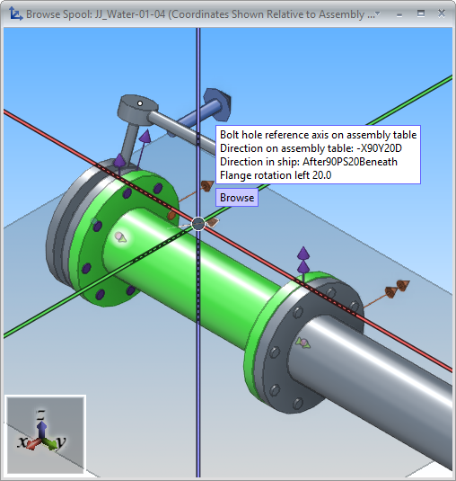
In the Spool group, click Assembly Table to open a view that shows the selected spool as placed on an assembly table. If you selected several spools, they are showed one at a time, and pressing Esc prompts you to select whether to show the next one or stop the browsing.
Spools that have flanges with bolt holes display a purple arrow to indicate reference axis direction in the standard position of the flange, and an orange arrow to indicate reference axis direction on the assembly table. These are paired with an arrow of the same color to indicate flange rotation in regard to the given reference axis direction. Move the cursor over an arrow to show direction details in a tooltip.
-
Purple arrows:
Bolt hole reference axis on standard position – This arrow shows the reference axis for the bolt holes in the standard position (basic two-holes-up rule – flange is square). Tooltip shows direction on assembly table and direction in the project's coordinate system.
Bolt hole symmetry axis in model – This arrow shows the bolt hole symmetry axis as rotated in the model, in reference to the standard position. Tooltip shows direction on assembly table, direction in the project's coordinate system, and flange rotation in reference to the standard position.
-
Orange arrows:
Bolt hole reference axis on assembly table – This arrow shows the direction in the plane of the nearest curve, or in the case of a straight branch, in the plane of the branch and the main run. Tooltip shows direction on assembly table and direction in the project's coordinate system.
Bolt hole symmetry axis on assembly table – This arrow shows the bolt hole symmetry axis as rotated in the model, in reference to the reference axis on assembly table. Tooltip shows direction on assembly table, direction in the project's coordinate system, and flange rotation in reference to the reference axis on assembly table.
In the assembly table view, you can do the following:
-
Use the normal navigation methods to rotate the view as needed. See Using view rotation tools in navigation.
-
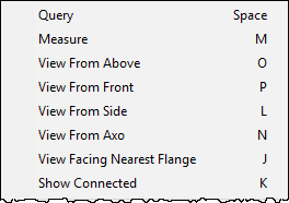
Right-click the view to open a context menu containing commands for querying and measuring, selecting a specific viewing direction, and showing also the connected objects in the view.

-
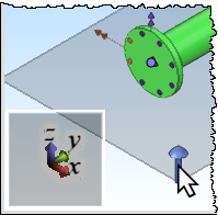
Click a blue main axis direction arrow to switch to the related viewing direction. For example, click the upward Z direction arrow to view the assembly table from the top.

Attributes

In the Spool group, click Attributes to open a dialog where you can specify which attributes to include in the selected pipe spools and to define their values.
For general information on the attribute editor, see Edit.
